I´m assuming you know how to set up an environment map, and how to use the Material Editor for this tutorial...
Step 1.
Open Material Editor and select an empty slot. Go to maps->diffuse and add a noise map - name this map "parent".
Step 2.
Apply the following settings to the noisemap and leave those i dont mention to their defaults.
Noise Parameters :
Noise Threshold High: 0.7
Now add a new noise map to the colour #1 map slot (its the black one) - and name this noisemap "child01"
Step 4.
Now go to the parent noisemap - and copy the child01 noisemap to the white map slot - and rename the copy "child02"
Step 3.
Apply thefollowing settings to the new noisemap - and leave those i dont mention to their defaults :
Coordinates : skip this part.
Noise Parameters :
Size : 1.0 (this defines the max size of the stars)
Noise Threshold Low : 0.69
Output :
RGB level : 5.0 (this makes the stars brighter)
Step 5.
In the child02 noisemap´s Noise Parameters, animate the Phase from 0 in frame 0 to 3 in frame 100.
By only animating the phase of one noisemap, you have ensured that there will always be some static stars, instead of having them all flicker.
Now apply the parent noisemap as environment map, specify output path and filename/type and hit render.
I know its not perfect, but it can be fitted to your specific needs with a little tweeking.

Showing posts with label Tutorials. Show all posts
Showing posts with label Tutorials. Show all posts
9.08.2007

5.31.2007
Volumetric lights (a.k.a. Kinetix logo effect)
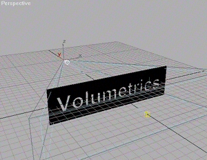
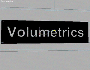
This is in fact an older tutorial, but I decided to rewrite it. I used to call it the Kinetix Logo Effect - its about volumetric lightning. With a little practice, you should be able to make cool text or logos, like these :


Let's get on with it...
Phase 1 :
Go to (create) -
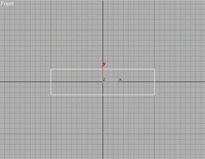
  (shapes), and using Keyboard Entry, create a rectangle in the FRONT viewport.
X=0, Y=0, Z=0
Width = 200
Height = 50
---------------
Phase 2 :
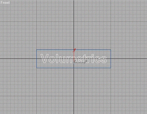
Once again go to create - shapes, and create the Text you want in the FRONT viewport. Place it in the middle of the Rectangle - this might take a little tweaking of the size of the Text-shape.
----------------
Phase 3 :
Go to (modifier), and add an Edit Spline modifier to the Rectangle.
Next up, attach the Text Shape to the rectangle by clicking - you should NOT be in sub-object mode for this operation.
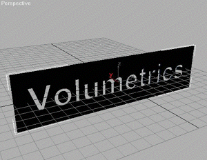
Then add a Bevel modifier (if you cant find it in the modifier list, click more)
Try these settings for starters (you can always alter them) :
Start Outline = 0,0
Level 1 :
Height = 1,0
Outline = 0,5
Check Level 2 :
Height = 1,0
Outline = 0,0
Check Level 3 :
Height = 1,0
Outline = -0,5
----------------
Phase 4 :
Go to (create) -  (lights), and in the TOP viewport, create a Target Spot
Place the spot about 200 units behind the Logo, and the Target about 80-100 in front of the Logo. Correct placement is important!
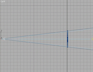
Now its time to fit the Spotlight Cone.
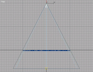
Select the Spot and go to , in the Target Spot rollout, go to the section with the Spotlight Parameters. Check Rectangle (instead of Circle), and by tweaking the Asp(ect) and the
Hotspot/Falloff make the Spotlight Cone fit like here (the lightblue is the Hotspot cone, and the darkblue the Falloff cone - and the Falloff cone should be approx 3,0 units bigger than the Spotlight Cone. It takes a little tweaking, I know, but you´ll get it right)
Done? Ok...
Now to setup the rest of the Spotlight Parameters.
Color = whatever color you like.
Multiplier = 2,0
And make sure to check the Cast shadows in the Shadow Parameter Rollout.
Time to set the perspective - move your PERSPECTIVE view around untill it looks a bit like the image above.
Try to get the Center of the Spotlight visible through a middle letter. You will know why when you see the rendering. Do NOT rotate the objects - use Arc Rotate, and Pan to set the perspective.
----------------
Phase 5 :
Now go to the Render menu, click Environment, and in the Atmosphere section, click Add, and select Volume Light from the list.
Click Pick Light, and select the Target Spot.
Settings for Volume Light (for now try these settings) :
Volume :
Density = 2
Check Use Attenuation Color
Check Filter Shadows : High
Sample Volume = 100% (if above options arent available, then de-check Auto)
Attenuation :
Start % = 100
End % = 80
Noise :
Check Noise On
Amount = 0,5
Check Turbulence
Size = 15
Check Wind From The : Back
- just leave the rest to its default settings.
----------------
Phase 6 :
Activate Perspective View, and hit (Quick Render). Be patient, volumetrics take a little while to render.
Looks pretty nifty, yeah?


Let's get on with it...
Phase 1 :
Go to
(create) - (shapes), and using Keyboard Entry, create a rectangle in the FRONT viewport.X=0, Y=0, Z=0
Width = 200
Height = 50
---------------
Phase 2 :
Once again go to create - shapes, and create the Text you want in the FRONT viewport. Place it in the middle of the Rectangle - this might take a little tweaking of the size of the Text-shape.
----------------
Phase 3 :
Go to
(modifier), and add an Edit Spline modifier to the Rectangle.Next up, attach the Text Shape to the rectangle by clicking
- you should NOT be in sub-object mode for this operation. Then add a Bevel modifier (if you cant find it in the modifier list, click more)
Try these settings for starters (you can always alter them) :
Start Outline = 0,0
Level 1 :
Height = 1,0
Outline = 0,5
Check Level 2 :
Height = 1,0
Outline = 0,0
Check Level 3 :
Height = 1,0
Outline = -0,5
----------------
Phase 4 :
Go to
(create) - (lights), and in the TOP viewport, create a Target SpotPlace the spot about 200 units behind the Logo, and the Target about 80-100 in front of the Logo. Correct placement is important!
Now its time to fit the Spotlight Cone.
Select the Spot and go to
, in the Target Spot rollout, go to the section with the Spotlight Parameters. Check Rectangle (instead of Circle), and by tweaking the Asp(ect) and theHotspot/Falloff make the Spotlight Cone fit like here (the lightblue is the Hotspot cone, and the darkblue the Falloff cone - and the Falloff cone should be approx 3,0 units bigger than the Spotlight Cone. It takes a little tweaking, I know, but you´ll get it right)
Done? Ok...
Now to setup the rest of the Spotlight Parameters.
Color = whatever color you like.
Multiplier = 2,0
And make sure to check the Cast shadows in the Shadow Parameter Rollout.
Time to set the perspective - move your PERSPECTIVE view around untill it looks a bit like the image above.
Try to get the Center of the Spotlight visible through a middle letter. You will know why when you see the rendering. Do NOT rotate the objects - use Arc Rotate, and Pan to set the perspective.
----------------
Phase 5 :
Now go to the Render menu, click Environment, and in the Atmosphere section, click Add, and select Volume Light from the list.
Click Pick Light, and select the Target Spot.
Settings for Volume Light (for now try these settings) :
Volume :
Density = 2
Check Use Attenuation Color
Check Filter Shadows : High
Sample Volume = 100% (if above options arent available, then de-check Auto)
Attenuation :
Start % = 100
End % = 80
Noise :
Check Noise On
Amount = 0,5
Check Turbulence
Size = 15
Check Wind From The : Back
- just leave the rest to its default settings.
----------------
Phase 6 :
Activate Perspective View, and hit
(Quick Render). Be patient, volumetrics take a little while to render.Looks pretty nifty, yeah?
5.15.2007
Barbed Wire Tutorial for 3dsMAX
Someone on 3dmaxer.dk posed the question "how do I make barbed wire in max?" I just blabbered an idea out, but it turned out to be pretty close to a step by step tutorial. So I´ve decided to make it easy for you guys. And here it is. Barbed Wire made easy. Remember though that this is just to illustrate the idea. To get the specific result YOU are looking for, you´ll have to tweak it yourself.
Now I´m primarily using splines and loftobjects (which initially consists of splines). The loftobject comes with its own UVW mapping system, which follows the path spline, making it a whole lot easier to texture.
This is what you should end up with...
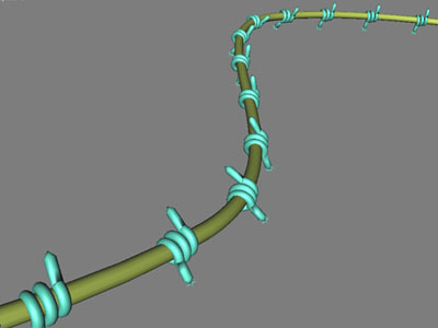
And this is what you need :

Lets get started.
First up go to create then shapes
  and create a helix with 2.5 turns. Make sure you raise the endpoint from the startingpoint to get a bit of spread.
Done? Good. Now go to the modify panel and with your helix selected, rightclick its name on the list in the modifier stack, and convert it to editable spline.
Now click the vertex subobject tab (it will not be yellow untill you click it)
take the first vertex of the helix and drag it away from the helix, and do the same to the last vertex.
This is the path for the loftobject.
Now exit vertex subobject mode (by clicking the tab again) and go back to create->shapes and this time make a circle. Size doesnt matter (riiiight!!) - do try to keep it a reasonable size compared to the helix.
If you´re not familiar with the loftobject, then basically what it does is to make one profile (in this case the circle) follow a path (in this case the helix) and make a mesh solid out of that.
Lets make a loft object :
 Select the Helix and go to create->geometry
  and from the dropdown menu select compund objects->loft.
Click get shape and select the circle (since you´re using the helix for path). And presto - a pointy-thingy. Not very pointy though is it? We´ll get to that in s minute. First there´s some settings you need to check in the loft object options. So select the freshly created loftobject, and go to the modify panel. In the options part of the loft object rollout, make your settings as showed here ---------->
Basically you´re just optimizing the loft object to use as few polygons as possible, to avoid dense meshes (as you will need a lot of these to make barbed wire).
Good then - now to make the ends pointy.
Go to the deformations rollout of the loft objects (yes, still in modify mode) - click scale and you´ll get a dialog like the one below...
...except you´ll have a straight line with only two dots placed at 0 and 100 on the line, and at level 100.
To make the extra two dots, click the create point tab (circled with yellow) and set two points similar to where i put mine (circled with blue). Now take the points at 0 and 100 and move them to level 0 (as seen circled with green).
What you´ve just done is make the loft object thinner along the path. Where 0 is the beginning and 100 is the end. In other words - with these new points - you made the pointythingy.....pointy.

 Ok - we have a pointythingy - now we need a line to copy it along (and to function as the actual line).
Once again go to create->shapes and this time make a line - give it three points for starters, and make it curve a bit.
There - now we need to add a million of the pointythingies (well - lets just settle with 25 or so).
We´ll be using the Snapshot Array tool, which copies or instances an object x times along a spline/path.
To do so select the pointythingy loftobject and
go to the motion panel and first mark the Position : Bezier position (Circled with blue and marked with yellow) - then click the get controller tab (the questionmark circled with blue) and from the list popping up, select path constraint.
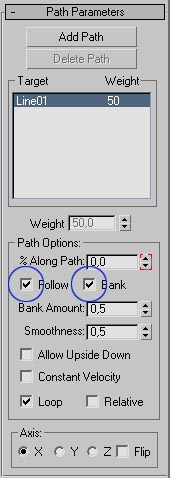 Click add path and select the line you created 2 minutes ago. Be sure to check follow and bank (circled with blue) - this will make the copies of the pointythingy follow the curvature of the line.
 Select the pointythingy loftobject with the path constraint controller recently added, and go to Tools-> Snapshot and you´ll get a similar dialog as this one.----------------------->
Make your settings match these and click ok. Choosing instance over copy, makes changes made to one pointythingy apply to all the others as well.
Now all you need is to select the line, go into the modify panel - check Renderable+Display render mesh, and set a thickness to your liking.
That should pretty much cover it. Add some textures and you should be set.
If you get in trouble, try downloading the Sample MAX5-file.
Copyright © 2003 - Nick Jensen - hatetank.dk - polygonpoop.dk
Now I´m primarily using splines and loftobjects (which initially consists of splines). The loftobject comes with its own UVW mapping system, which follows the path spline, making it a whole lot easier to texture.
This is what you should end up with...
And this is what you need :
Lets get started.
First up go to create
then shapes and create a helix with 2.5 turns. Make sure you raise the endpoint from the startingpoint to get a bit of spread.Done? Good. Now go to the modify panel
and with your helix selected, rightclick its name on the list in the modifier stack, and convert it to editable spline.Now click the vertex subobject tab
(it will not be yellow untill you click it)take the first vertex of the helix and drag it away from the helix, and do the same to the last vertex.
This is the path for the loftobject.
Now exit vertex subobject mode (by clicking the tab again) and go back to create->shapes and this time make a circle. Size doesnt matter (riiiight!!) - do try to keep it a reasonable size compared to the helix.
If you´re not familiar with the loftobject, then basically what it does is to make one profile (in this case the circle) follow a path (in this case the helix) and make a mesh solid out of that.
Lets make a loft object :
Select the Helix and go to create->geometry and from the dropdown menu select compund objects->loft.Click get shape and select the circle (since you´re using the helix for path). And presto - a pointy-thingy. Not very pointy though is it? We´ll get to that in s minute. First there´s some settings you need to check in the loft object options. So select the freshly created loftobject, and go to the modify panel. In the options part of the loft object rollout, make your settings as showed here ---------->
Basically you´re just optimizing the loft object to use as few polygons as possible, to avoid dense meshes (as you will need a lot of these to make barbed wire).
Good then - now to make the ends pointy.
Go to the deformations rollout of the loft objects (yes, still in modify mode) - click scale and you´ll get a dialog like the one below...
...except you´ll have a straight line with only two dots placed at 0 and 100 on the line, and at level 100.
To make the extra two dots, click the create point tab (circled with yellow) and set two points similar to where i put mine (circled with blue). Now take the points at 0 and 100 and move them to level 0 (as seen circled with green).
What you´ve just done is make the loft object thinner along the path. Where 0 is the beginning and 100 is the end. In other words - with these new points - you made the pointythingy.....pointy.
Ok - we have a pointythingy - now we need a line to copy it along (and to function as the actual line).Once again go to create->shapes and this time make a line - give it three points for starters, and make it curve a bit.
There - now we need to add a million of the pointythingies (well - lets just settle with 25 or so).
We´ll be using the Snapshot Array tool, which copies or instances an object x times along a spline/path.
To do so select the pointythingy loftobject and
go to the motion panel
and first mark the Position : Bezier position (Circled with blue and marked with yellow) - then click the get controller tab (the questionmark circled with blue) and from the list popping up, select path constraint. Click add path and select the line you created 2 minutes ago. Be sure to check follow and bank (circled with blue) - this will make the copies of the pointythingy follow the curvature of the line.Select the pointythingy loftobject with the path constraint controller recently added, and go to Tools-> Snapshot and you´ll get a similar dialog as this one.----------------------->Make your settings match these and click ok. Choosing instance over copy, makes changes made to one pointythingy apply to all the others as well.
Now all you need is to select the line, go into the modify panel - check Renderable+Display render mesh, and set a thickness to your liking.
That should pretty much cover it. Add some textures and you should be set.
If you get in trouble, try downloading the Sample MAX5-file.
Copyright © 2003 - Nick Jensen - hatetank.dk - polygonpoop.dk
5.10.2007
Fish eye lens tutorial for 3dsMAX
For this tutorial, I assume you have some knowledge with cameras and materials in 3DsMAX (any version should do).
3DsMAX does not come with the ability to do a fisheye lens effect (well - it does if you follow this tutorial). There´s a long range of expensive plugins and 3rd party renderers that will do this - probably more accurate than this tut too, but at least this one costs nothing ;)
I don´t know if someone else have thought of this, and I am in fact merely "re-inventing the wheel", but I think its a good tip still.
Setup - Top view
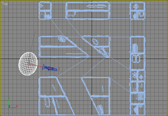 Ok - it´s really not that tricky. As you can see from the Topview picture, all I´ve done is place a sphere in front of the camera.
"But the camera is with its back to the scene".
Indeed - and thats because you´re filming the reflection of the scene, in the sphere.
The sphere has been given a Chrome-material, with NO highlights (important!). And i have aligned it to the camera, both with position and orientation - then I´ve moved along the sphere´s local Z-axxis to a little bit in front of the camera, and scaled it along its local Z-axxis.
The scaling allows you to determine the amount of the fisheye effect.... The more round or pointy, the stronger the effect - and the flatter (like an M&M) the less the effect.
Setup - Perspective view
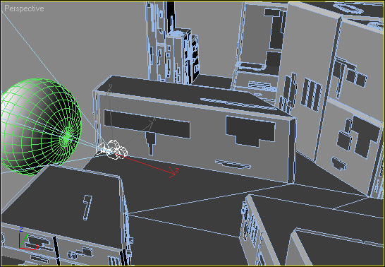 You can link the sphere to the camera, or the other way around, once you have them positioned and aligned properly together. You need to make sure that the sphere covers the entire frame (corner to corner) - or you´ll get weird results.
For animating purposes, you need to steer clear of obstacles - remember, this is a reflection and objects can conflict with the chromesphere. If you find that the sphere is too big to pass a corridor or other obstacle, you can scale down the sphere (uniformly) and move it closer to the camera.
Thats it really. But there´s some things to take into consideration as well :
Std. MAX render
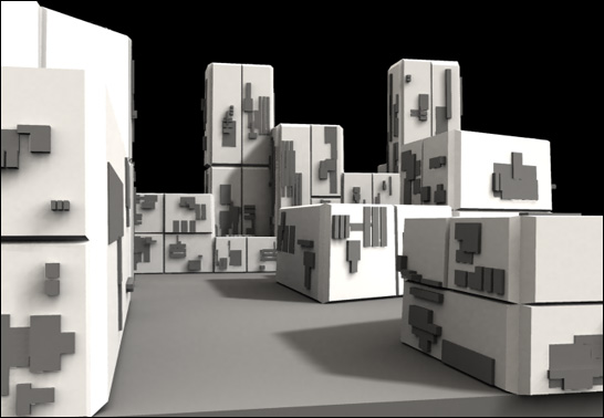 1. You are capturing a reflection - so everything will be mirrored. Flip the rendered images/movies in whatever image/video-editing software you normally use.
2. Since you´re shooting a reflection, stuff like GI and other advanced lighting solutions, will need more samples to avoid graininess - also higher Raytracing quality might help.
3. You will kinda be animating backwards - and it takes a little getting used to.
Fisheye rendering
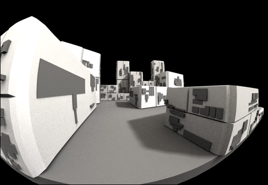 4. You can´t get a proper viewport preview, since this method relies on materials. If in doubt, do some testrenderings.
5. To avoid the ChromeSphere reflecting in other reflective surfaces of the scene (like a window or similar), use the Local Exclude option in the Raytrace options of the material. Exclude from both illumination and shadow casting. Also, depending on your render engine, you might have to exclude the ChromeSphere from GI solutions and/or Skylights.
6. I have not tested this method on that many scenes - so I cannot guarantee it will work with YOUR setup. But give it a go - and I´d love to get some feedback, and see your results, if you use this tutorial.
Enjoy!
Oh, and be sure to get the Mirror Image render effect plugin from Boomerlabs - to easily flip your images from within MAX.
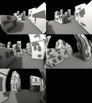 Copyright 2004 - Nick Jensen
3DsMAX does not come with the ability to do a fisheye lens effect (well - it does if you follow this tutorial). There´s a long range of expensive plugins and 3rd party renderers that will do this - probably more accurate than this tut too, but at least this one costs nothing ;)
I don´t know if someone else have thought of this, and I am in fact merely "re-inventing the wheel", but I think its a good tip still.
Setup - Top view
Ok - it´s really not that tricky. As you can see from the Topview picture, all I´ve done is place a sphere in front of the camera. "But the camera is with its back to the scene".
Indeed - and thats because you´re filming the reflection of the scene, in the sphere.
The sphere has been given a Chrome-material, with NO highlights (important!). And i have aligned it to the camera, both with position and orientation - then I´ve moved along the sphere´s local Z-axxis to a little bit in front of the camera, and scaled it along its local Z-axxis.
The scaling allows you to determine the amount of the fisheye effect.... The more round or pointy, the stronger the effect - and the flatter (like an M&M) the less the effect.
Setup - Perspective view
You can link the sphere to the camera, or the other way around, once you have them positioned and aligned properly together. You need to make sure that the sphere covers the entire frame (corner to corner) - or you´ll get weird results.For animating purposes, you need to steer clear of obstacles - remember, this is a reflection and objects can conflict with the chromesphere. If you find that the sphere is too big to pass a corridor or other obstacle, you can scale down the sphere (uniformly) and move it closer to the camera.
Thats it really. But there´s some things to take into consideration as well :
Std. MAX render
1. You are capturing a reflection - so everything will be mirrored. Flip the rendered images/movies in whatever image/video-editing software you normally use.2. Since you´re shooting a reflection, stuff like GI and other advanced lighting solutions, will need more samples to avoid graininess - also higher Raytracing quality might help.
3. You will kinda be animating backwards - and it takes a little getting used to.
Fisheye rendering
4. You can´t get a proper viewport preview, since this method relies on materials. If in doubt, do some testrenderings.5. To avoid the ChromeSphere reflecting in other reflective surfaces of the scene (like a window or similar), use the Local Exclude option in the Raytrace options of the material. Exclude from both illumination and shadow casting. Also, depending on your render engine, you might have to exclude the ChromeSphere from GI solutions and/or Skylights.
6. I have not tested this method on that many scenes - so I cannot guarantee it will work with YOUR setup. But give it a go - and I´d love to get some feedback, and see your results, if you use this tutorial.
Enjoy!
Oh, and be sure to get the Mirror Image render effect plugin from Boomerlabs - to easily flip your images from within MAX.
Copyright 2004 - Nick Jensen
Subscribe to:
Posts (Atom)